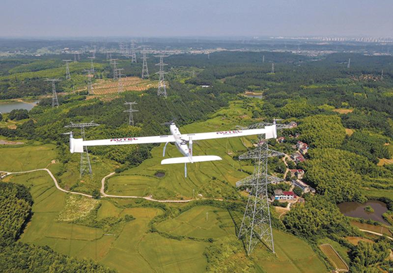
In summary, power line inspection drones generally possess the following key technologies:
1. Environmental Intelligent Perception Technology
Achieving environmental perception by drones is a prerequisite for intelligent and autonomous inspection, requiring the drone to perceive its surrounding environment under all-weather conditions.
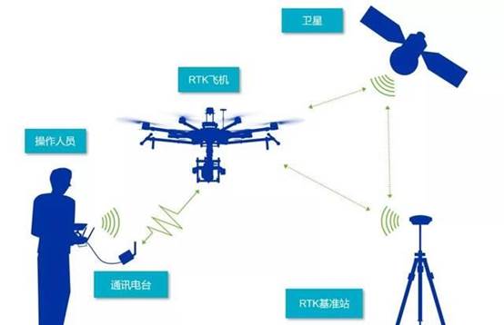
Simultaneous Localization and Mapping (SLAM) technology involves a moving entity equipped with environmental perception sensors, creating a map or incrementally updating and optimizing a map using sensor observations of the environment in an unknown environment or a known map. In SLAM algorithms, localization is performed within the created map of the unknown environment, and the accurate creation of the unknown environment map depends on the accuracy of the drone’s localization algorithm; localization and mapping are closely related and interdependent. Based on the main sensor types, SLAM technology can be divided into visual and laser types. Among them, LiDAR has fast processing speed and high data accuracy, and can efficiently respond to scene changes in dynamic environments. Mainstream manufacturers use laser SLAM to obtain on-site laser point cloud maps, and use inter-frame matching, loop closure detection, and other methods to scan surrounding environmental information to form laser point cloud data. Based on the first frame of data, and according to the principle of superimposing subsequent frames of point cloud data onto the previous frames, a global map is formed.
The laser SLAM framework generally consists of four modules: front-end scan matching, back-end optimization, loop closure detection, and map construction. The front-end is the core step. Its content is to estimate the current frame’s pose using the relationship between adjacent frames, given the previous frame’s drone pose; the front-end can provide the drone’s pose and map for a short period, but due to unavoidable error accumulation, the back-end optimizes the odometry and map information after long-term incremental scan matching; loop closure is responsible for reducing the drift of the global map by detecting loops to generate a globally consistent map; map construction is responsible for generating and maintaining the global map.
2. Optimal Path Planning Technology. This refers to intelligently planning a path from the starting point to the target point through environmental perception, ensuring that the path is as short and reasonable as possible. For path planning of inspection drones, the key issues are: first, the global path planning problem. Given global environmental information, how to plan a feasible flight range and avoid static obstacles through reasonable route settings. Second, the shortest path search problem. For the planned path, how to find the shortest distance between two points in the map. The most direct and feasible method for the former is manual path planning, which involves designing routes manually based on the actual environment, taking into full consideration the distribution range of static obstacles, and setting the navigable area for the inspection drone. This method is suitable for map environments with clearly defined drone flight paths, and manual route setting requires the use of visualization tools. Besides manual setting, the free space method uses structural space methods to model the surrounding environment and treats the inspection drone as a point mass, ensuring that it avoids obstacles and moves from the starting point to the target point in the modeled environment. Simultaneously, based on artificial intelligence research, various intelligent path planning methods such as ant colony algorithms, genetic algorithms, neural network algorithms, and fuzzy control algorithms are used.
Regarding shortest path search, the optimal algorithm for finding the shortest path from the starting point to the target point is determined based on the prior map environment model and global path information. Traditional path planning algorithms load relevant environmental information into the algorithm in advance, depending on the drone inspection task and environment. The AI algorithm is a commonly used method that uses a cost function to describe the cost of a path between two points on a map and recursively searches for the path with the minimum cost. Dijkstra’s algorithm is an algorithm in graph theory for finding the shortest path, mainly used to find the shortest path from one point to all other points. The Floyd algorithm is a dynamic programming algorithm that can solve the shortest path problem between any two points in a directed graph.
Global path planning algorithms include: determining the shortest path from a starting point (i.e., determining the shortest path to a destination); determining the shortest path between a starting point and a destination (i.e., the global shortest path problem), using algorithms such as Dijkstra’s algorithm and the AI algorithm.
Because traditional path planning algorithms have difficulty solving problems involving high-dimensional space, nonlinearity, and mixed discrete and continuous variables in drone inspection path planning, intelligent optimization path planning algorithms have emerged. Currently, widely used intelligent optimization path planning algorithms include genetic algorithms and particle swarm optimization algorithms.
3. Image Autonomous Acquisition Technology. In inspection, the most important aspect is acquiring images of equipment and instruments. Reading on-site instrument readings presents significant difficulties. Due to cost and historical reasons, most on-site instruments are analog indicators and do not have the remote transmission capabilities of smart instruments. Therefore, the inspection drone must use computer vision methods to read the readings. Some of these readings are digital, others are pointer-based, and the working conditions and types of instruments vary at each station. There are also various challenges such as different outdoor lighting conditions, different drone shooting angles, and varying degrees of occlusion and blurring, all of which make it extremely difficult for drones to perform instrument detection and reading recognition functions.
Both the drone’s positioning and navigation accuracy and the gimbal control accuracy have certain errors. When the drone performs inspection tasks, the visible light camera retrieves camera parameters and acquires equipment images. This can result in the equipment not being in the center of the field of view, or even being outside the field of view, leading to failure in acquiring the equipment image. Therefore, a visual servo control technology based on an equipment template library has been developed. Based on the drone’s gimbal preset position, the gimbal is rotated to adjust the camera’s focal length and magnification, creating a small image of the equipment in a large field of view in automatic inspection mode. This image is then compared with the equipment images in the template library to extract the pixel difference of the target image position, calculate the horizontal and vertical angular deviations in the field of view, and control the gimbal rotation to shift the target towards the center of the field of view, correcting for target point deviations caused by navigation and gimbal control errors. Although this correction process can correct deviations, it increases inspection time and reduces inspection efficiency. How to quickly perform servo correction has become a key focus for improving current drone technology.
For instrument detection, cascaded detectors are one of the most widely used and classic object detectors. The selective search strategy calculates many candidate regions for multi-object detection in an image, which is the basis for subsequent deep learning-based detection methods.
The most important task in inspection is collecting equipment instrument information. After the drone reaches the designated point using a positioning and navigation algorithm, it needs to detect whether there is a corresponding target equipment instrument in the image. If not detected, the drone’s attitude is adjusted, and the image is reacquired until the corresponding target equipment instrument is detected. Otherwise, if the equipment instrument is still not detected after multiple adjustments, it is treated as an abnormal situation and transmitted back to the control room via the network for manual intervention. If the corresponding target equipment instrument has been detected in the input image, the detected position is input into the subsequent recognition algorithm to extract its scale area and pointer area, and finally, the recognition module identifies the pointer reading and digital reading of the instrument.
4. Sound Recognition Technology. Drones are generally equipped with microphones that can collect equipment sounds. Equipment detection methods based on sound signals allow inspection drones to “listen” to the equipment status on behalf of humans, enabling automatic detection of equipment anomalies and environmental noise analysis. However, complete sound recognition still presents difficulties. Firstly, sound acquisition is difficult; the environment often contains a large number of devices, and the sounds from various devices and environmental noise interfere with each other, making it difficult to distinguish them. Secondly, there are no sound recognition standards; there are no standardized criteria for device sound recognition. After extracting feature values from the collected sounds, it is impossible to determine whether a device is abnormal based on the sound samples.
Sound is considered a carrier similar to a wave, with information carried on the waveform. Sound recognition is a technology that takes serialized data carrying information over a period of time and outputs it in a way that allows humans to obtain important information.
The preprocessing of sound data involves signal processing and feature extraction. Before building an acoustic model, preprocessing techniques are used to eliminate noise and enhance the channel in the experimental data. The audio signal is transformed from the time domain to the frequency domain through processing, so that the acoustic model can obtain more effective feature vectors from the processed signal. These feature vectors are then converted into acoustic model scores, which are matched with the language model scores obtained from the language model. Finally, a decoding search module combines these two scores, and the word sequence with the highest score is selected as the optimal recognition structure. This is the principle of sound recognition.
Sound data processing consists of four processes: feature extraction, acoustic model, language model, dictionary, and decoding. To efficiently extract sample signal features, preprocessing work such as filtering and noise reduction is required on the sample sound signal to separate the target signal from the original sound signal; feature extraction converts the sound signal from the time domain to the frequency domain, providing relevant feature vectors for the acoustic model; the acoustic model calculates the relative score of the feature vector on the acoustic features, and finally provides a dictionary to decode the obtained word sequence and obtain the corresponding text information.
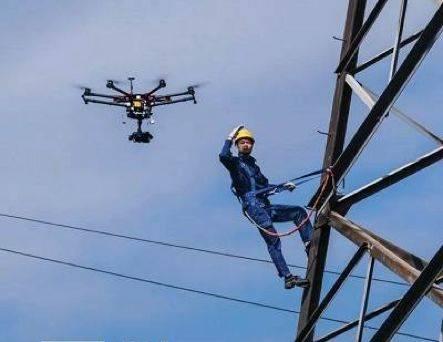
5. Infrared temperature measurement technology. Inspections generally involve visual and auditory checks of equipment operation, with visual inspection being the primary method. Later, infrared temperature measurement devices were used to detect thermal defects and ensure equipment safety. Drones equipped with infrared thermal imagers can perform infrared temperature measurement of equipment. This replaces the original manual method of using handheld infrared thermal imagers to detect equipment hotspots, and replaces manual on-site observation with remote monitoring, reducing labor intensity and ensuring personnel safety.
Infrared image temperature recognition technology is currently quite mature. It determines the temperature of an object based on its infrared radiation. Devices are divided into cooled focal plane thermal imagers and uncooled focal plane thermal imagers. The equipment’s temperature is monitored based on thermal radiation, ensuring that the equipment operates within its normal working temperature range. The mechanism works as follows: first, the sensor unit collects the heat generated during the infrared temperature measurement process; then, the collected radiant heat is transmitted as signal data through the infrared detection equipment and signal processing unit; finally, the signal data is displayed by the display unit. Equipment maintenance personnel then determine whether the equipment is operating within the normal range based on the temperature signal information. Simultaneously, the infrared temperature measurement data enables real-time monitoring of site equipment, allowing for accurate identification of fault locations.
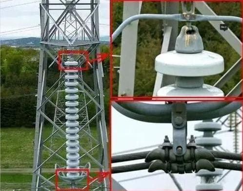
6. Partial Discharge Detection Technology. This primarily involves detecting discharges between insulating media. Methods include optical detection, ultrasonic detection, transient ground wave detection, and ultra-high frequency methods.
Optical detection uses a photomultiplier to detect the light signals generated during discharge. This is the most sensitive detection method, but due to the strong absorption of photon signals by materials such as glass and SF6, it cannot detect partial discharges through switchgear. This means that this method can only be used for offline detection and cannot achieve online monitoring.
Ultrasonic detection. The ultrasonic signals excited by partial discharge have a wide bandwidth and can be detected outside the power cabinet using acoustic emission sensors. Because ultrasonic detection is non-invasive, it does not affect the electromagnetic field generated by partial discharge inside the equipment and is less affected by external noise. However, because the acoustic signal attenuates when passing through insulators and SF6, partial discharges may not be accurately detected in some cases.
Transient ground wave detection. When high-voltage electrical equipment experiences partial discharge, the breakdown short circuit of the local electric field causes a portion of the charge in the conductors at both ends to be released, propagating as electromagnetic waves along the conductor, forming a current, accumulating on the inner surface of the casing shield, and forming a transient voltage pulse signal at the discontinuity of the shield. The transient voltage pulse signal is then coupled out through a capacitor, amplified, and detected after noise reduction. This method has a detection frequency band of 1 to 25 MHz and high detection sensitivity.
Ultra-high frequency detection method. The ultra-high frequency (UHF) generated by partial discharge ranges from 300 MHz to 3 GHz, while the frequency of noise interference is below 500 MHz. Therefore, the UHF method has strong anti-interference capabilities. However, since the UHF signal attenuates significantly with increasing distance from the partial discharge source, the sensor needs to be close to the source, making it unsuitable for partial discharge detection in switchgear.
Based on extensive experience in detecting discharges in high-voltage power cabinets, we employ ultrasonic and ground wave detection methods. By complementing and comparing these two methods, we broaden the detection bandwidth and improve detection sensitivity. Combined with trend analysis over time, this enables accurate monitoring of partial discharge in equipment.
Leave a Reply